Transforms
Since last when making a few renders that the shading was a bit off. The lighting seamed to come from the wrong direction, this was fixed.
The next step we said was to “implement the twisting nature”. This is not done by modelling the individual fibers being twisted, as was previously thought. Instead highlights are added and they are effected by the twisting nature by changing the shape of the highlights. These highlights follow the “ideal specular highlight line” as described in Irawan. A derivation and a more through description of this is to follow…
After a quick implementation of these highlights we noticed that the highlights seemed of and not where we expected them to be on the individual yarn segments. This was fixed and yet again it was a problem with how we performed our coordinate-transformations.
We set up a good test scene with light coming from a small light source in a distinct direction. The test scene uses this pattern. The fixes can be seen below…
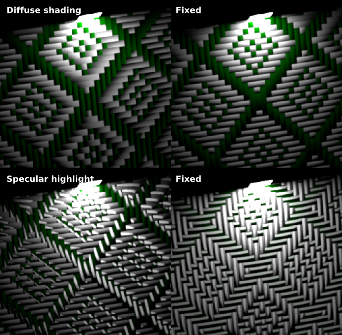
After many alterations and many attempts at getting the model to behave correctly it finally appears to behave.
This seems like good oppurtunity to go the through coordinate transformations that are currently performed in the code to make it clear what is going on.
Walkthrough
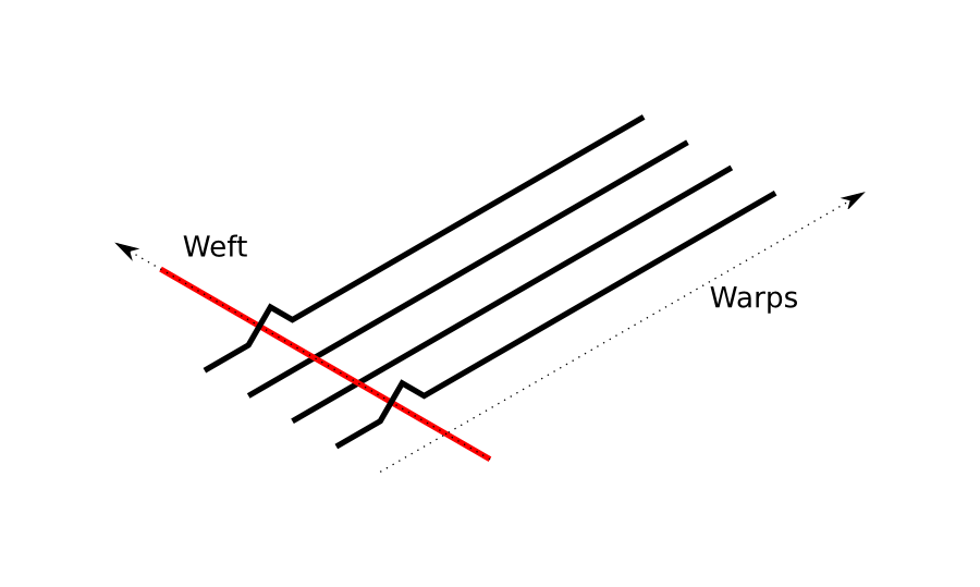
First of all we follow the convention in these derivations that warp yarns are vertical and weft yarns are horizontal.
The code in cloth.cpp at the time of writing can be seen here.
Our shader gets invoked through either the eval method or the sample method and has to return a Spectrum-value. Sample is called when only \( \vec{w_i} \) is known and eval when both \( \vec{w_i} \) and \( \vec{w_o} \) are known. Passed along to these methods is a parameter of type BSDFSamplingRecord called bRec. Through this varaible mitsuba passes information such as intersection point and surface normal. Additionally, mitsuba passes shading coordinats that are local to the surface, so called u-v coordinates, through bRec.
Using the coordinates for the intersection point we can get data about the pattern at the current point. This is given by the getPatternData(bRec.its) call, which takes the current intersection as a parameter.
eval
Spectrum eval(const BSDFSamplingRecord &bRec, EMeasure measure) const {
    if (!(bRec.typeMask & EDiffuseReflection) || measure != ESolidAngle
            || Frame::cosTheta(bRec.wi) <= 0
            || Frame::cosTheta(bRec.wo) <= 0)
        return Spectrum(0.0f);

    // Perturb the sampling record, in turn normal to match our thread normals
    PatternData pattern_data = getPatternData(bRec.its);
    Intersection perturbed(bRec.its);
    perturbed.shFrame = pattern_data.frame;

    Vector perturbed_wo = perturbed.toLocal(bRec.its.toWorld(bRec.wo));
    float diffuse_mask = 1.f;
    //Diffuse will be black if the perturbed direction
    //lies below the surface
    if(Frame::cosTheta(bRec.wo) * Frame::cosTheta(perturbed_wo) <= 0){
        diffuse_mask = 0.f;
    }

    Spectrum specular(m_specular_strength*m_specular_normalization*
            specularReflectionPattern(bRec.wi, bRec.wo,
                pattern_data,bRec.its));
    return m_reflectance->eval(bRec.its) * diffuse_mask *
        pattern_data.color*(1.f - m_specular_strength) *
        (INV_PI * Frame::cosTheta(perturbed_wo)) +
        m_specular_strength*specular*Frame::cosTheta(bRec.wo);
}
From the getPatternData() call we get a perturbed shading-frame which we use to get the angle perturbed_wo used in
return m_reflectance->eval(bRec.its) * diffuse_mask
  * pattern_data.color*(1.f - m_specular_strength)
  * (INV_PI * Frame::cosTheta(perturbed_wo)) + ...
.
getPatternData
The first thing that is done is thata new coordinate system is defined, the looped uv coordinates, that is looped from 0 to 1 based on the passed uv coordinates. This allows us to later much easier traverse the matrix defining the pattern. The two last if clauses make sure that the coordinate repeat the expected way and do not mirror at the origin.
//Set repeating uv coordinates.
float u_repeat = fmod(its.uv.x*m_uscale,1.f);
float v_repeat = fmod(its.uv.y*m_vscale,1.f);
//TODO(Vidar): Check why this crashes sometimes
if (u_repeat < 0.f) {
    u_repeat = u_repeat - floor(u_repeat);
}
if (v_repeat < 0.f) {
    v_repeat = v_repeat - floor(v_repeat);
}
Next the length of the yarn-segment we are currently on is calculated. Soon after a new set of coordinates are defined. The yarn local coordinats x and y that go from -1 to 1. These are defined in a way so that x is always going along the short-side of the current yarn-segment and y is going along the long-side of the current yarn-segment. Note that this means that x and y change roles depending on if the current yarn is a warp or weft, specifically the values of x and y are swapped when the current yarn segment is weft.

//Yarn-segment-local coordinates.
float l = (steps_left_warp + steps_right_warp + 1.f);
float y = ((v_repeat*(float)(m_pattern_height) - (float)pattern_y)
+ steps_left_warp)/l;
float w = (steps_left_weft + steps_right_weft + 1.f);
float x = ((u_repeat*(float)(m_pattern_width) - (float)pattern_x)
+ steps_left_weft)/w;
//Rescale x and y to [-1,1]
x = x*2.f - 1.f;
y = y*2.f - 1.f;
//Switch X and Y for warp, so that we always have the yarn
// cylinder going along the y axis
if(!current_point.warp_above){
float tmp1 = x;
float tmp2 = w;
x = -y;
y = tmp1;
w = l;
l = tmp2;
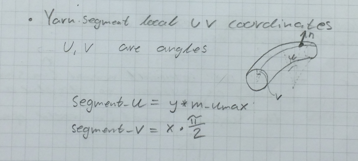
}Next uv-segment coordinates are defined. Here u describes the angle to the current point along the long-side of the yarn segment and v describes the angle of the current point along the short-side of the yarn segment. We have two methods of doing this, as described in this post.
//Calculate the yarn-segment-local u v coordinates along the curved cylinder
// there are two methods of performing this transformation.

//More exact transformation
segment_u = asinf(x*sinf(m_umax));
segment_v = asinf(y);

//Irawans approximation
float segment_u = y*m_umax;
float segment_v = x*M_PI_2;
See the following illustration.
From this the normal of the thread surface in these local coordinates can be calculated.
//Calculate the normal in thread-local coordinates
Vector normal(sinf(segment_v), sinf(segment_u)*cosf(segment_v),
    cosf(segment_u)*cosf(segment_v));
In order to go further we have to revert our swapping that was done to keep the x axis along the short-side of the yarn-segment. The x and y componenet of the normal are swapped again if we are on a weft. This makes sure that this normal and any future normals that are going to be calculated will be in a coherent coordinate-system.
//Transform the normal back to shading space
if(!current_point.warp_above){
    float tmp = normal.x;
    normal.x = normal.y;
    normal.y = -tmp;
}
Next we want to consturct a coordinate frame that is the shading frame but perturbed by our thread normal. In practice we use our calculated thread normal to displace the axis-vectors that are given by mitsuba. Given our calculated our thread normal \( \vec{n} \), the surface normal as given by mitsuba \( \vec{n_s} \) and the partial derivates of the surface normal \( \frac{\partial \vec{n_s}}{\partial v} \) and \( \frac{\partial \vec{n_s}}{\partial u} \) we can construct this displaced frame by getting the perturbed partial derivates dpdpv and dpdu.
dpdv is the vector pointing in the \( \hat{v} \) direction of our shading space \( \frac{\partial \vec{n_s}}{\partial v} \) expressed in world coordinates but perturbed by the term \( \vec{n_s} (-(\vec{n})_y)) \). This term is the surface normal scaled by the y-component of the thread normal \( \vec{n} \).
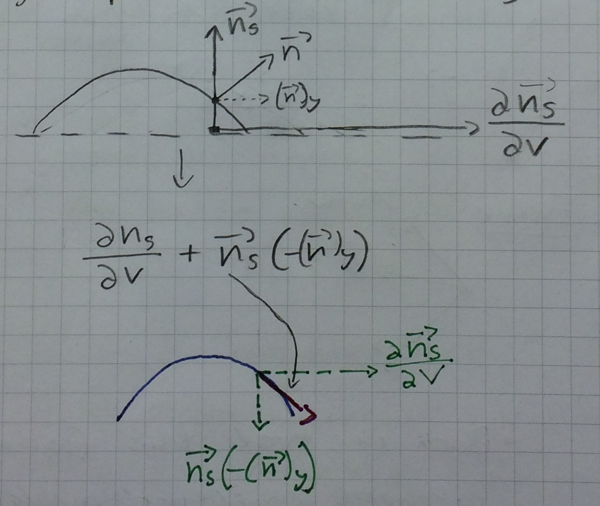
The last term \( \vec{n_s} (\vec{n_s} \cdot \frac{\partial \vec{n_s}}{\partial v}) \) adjusts the shading frame so that mitsubas interpolation for the smooth shading still works.
The same is done for dpdu.
Float dDispDu = normal.x;
Float dDispDv = normal.y;
Vector dpdv = its.dpdv + its.shFrame.n * (
        -dDispDv - dot(its.shFrame.n, its.dpdv));
Vector dpdu = its.dpdu + its.shFrame.n * (
        -dDispDu - dot(its.shFrame.n, its.dpdu));
// dpdv & dpdu are in world space
From these vectors the new frame can be constructed:
//set frame
Frame result;
result.n = normalize(cross(dpdu, dpdv));

result.s = normalize(dpdu - result.n
        * dot(result.n, dpdu));
result.t = cross(result.n, result.s);

//Flip the normal if it points in the wrong direction
if (dot(result.n, its.geoFrame.n) < 0)
    result.n *= -1;
Finally the newly constructed frame and some of our coordiantes are saved and passed on for later use.
specularReflectionPattern
We will talk about this later.