Thread segments
The state in which we left our rudimentary shader allowed it to color the surface of an object according to the specified pattern through a wif file. This was a good initial step for our shader and nicely demonstrates our initial work on reading and interpreting wif files. (link to prev. post.)
Looking forward, we want our shader to change the behaviour of light interactions based on these patterns and thread behaviour and not just color the surface in a square by square fashion, as is currently the case. In order to do this, we need to, as a first step, we need to be able to replace a segment of connected areas in the pattern with a mathematical representation of a thread.
To do this we looked at this mathematical representation, after which we looked at getting the shader to identify the connected segments in the pattern.
But first we need to define what we mean by a segment.
Definition: Connected Segments
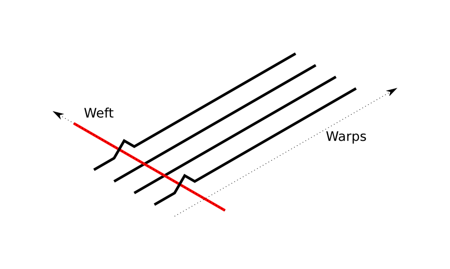
We degine a connected warp segment in the pattern as follows. In the following illustration, taken from this paper by Irawan, Marschner, we see that visible warp threads are considered connected if they are are next to each other. The segment ends when the warp is no longer visible. The same applies for wefts.
Rudimentary mathematical threads
Our representation models the thread as a bent cylinder. The goal is to get the surface normal of this thread which can then be used for lighting.
Given coordinates local to a specific segment on the pattern we can create a transformation that maps these to angles used to describe locations on the bent cylinder. Here we treat \(u\) as the angle used to describe the position across the long side of the thread while \(v\) is the angle describing the position across the short side of the thread. Given these angles we can easily calculate the surface normal using the following expression.
\begin{equation} \vec{n}(u,v) = \begin{bmatrix} \sin{v} \\ \sin{u} \cos{v} \\ \cos{u} \cos{v} \end{bmatrix} . \end{equation}
The actual transformation to uv is performed using the following expressions…
In the paper by Irawan this is the proposed coordinate transformation,
\begin{align} u &= \frac{u_{max}}{l} y \\ v &= \frac{\pi}{w} x, \end{align} This transformation is an approximation and does not take into account forshortening effects.
In order to investigate the effect that these approximations make, we derive the transformation for a real bent cylinder,
\begin{align}
u &= \arcsin{(2\frac{y}{l}\sin(u_{max}))} \\
v &= \arcsin{(2\frac{x}{w})}
\end{align}
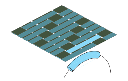
We will continue to compare these two methods in our implementation, but as a first comparison we used these two mappings to displace a rectangular plane in Houdini.

Left shows the coordinate transformation with simplifications as proposed by Irawan, Marschner. Right shows our transformation without simplifications, therby more closely resembling a bent cylinder, note that this mapping requires expensive arcsin calls.
Connected strips
Currently, our shader simply uses coordinates local to the object surface (so called uv coordinates) provided by mitsuba that have then been scaled and wrapped to repeat over the interval [0, 1]. These coordinates are used to look up data about the pattern at the given position, such as color and whether the warp or weft is visible. We now want connected warp segments and weft segments to be replaced by a mathematical representation of a thread which takes into account the bending nature of the thread. This means that the amount of bend along the long-side will be different depending on the length of the current segment.
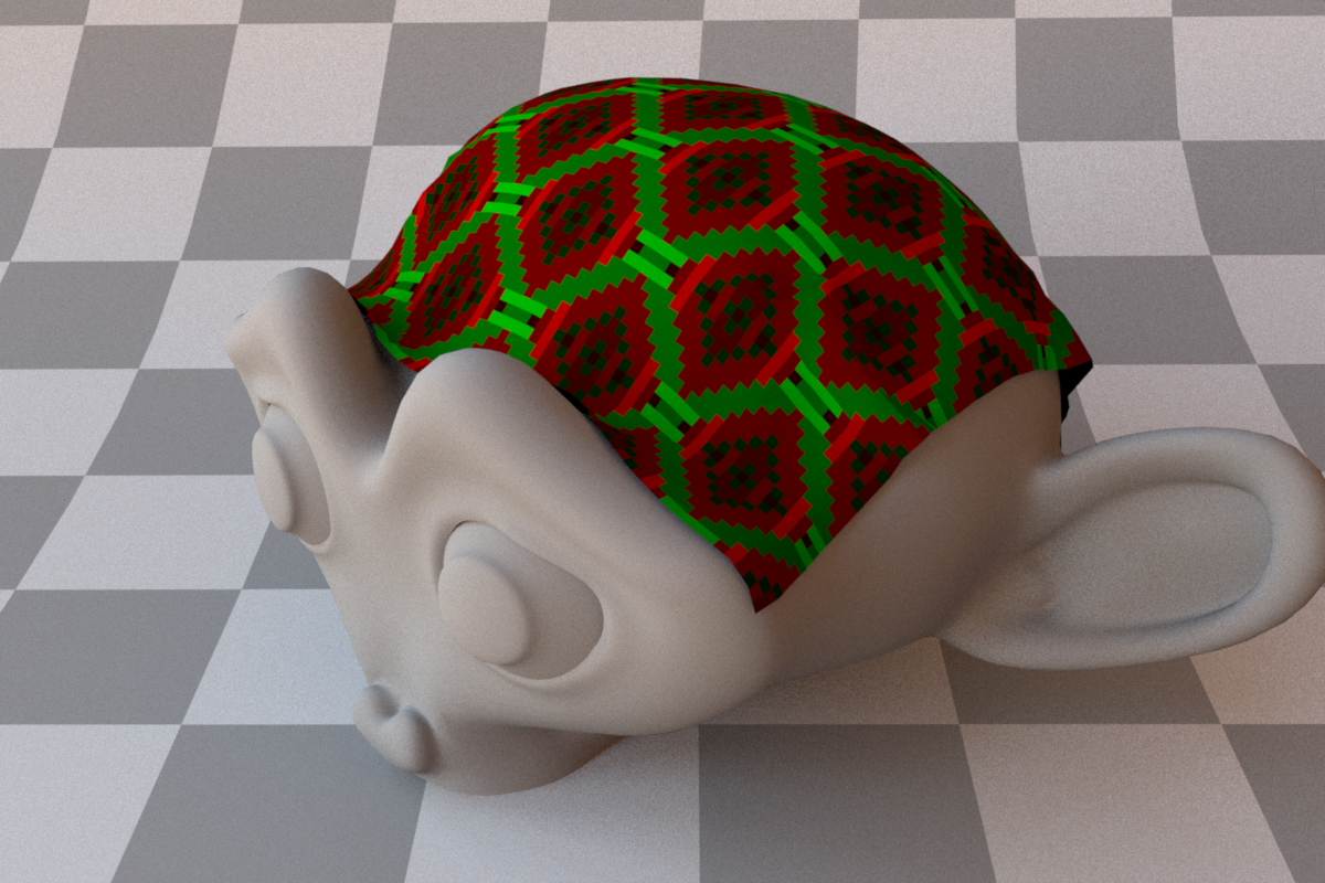
In order to know where we would be on a mathematical thread representation at a given position we first need know how long the piece of thread is that we are currently on. The shader code was modified to allow us to know the length of the current thread. To accomplish this a loop is performed for warps and wefts separately. To demonstrate, lets assume a position is given where the current pattern data states that the warp thread is visible, the loop will successively check the next pattern positions (in both directions, “left” and “right”) along the warp axis until it encounters a position where the warp is no longer visible. This gives us information about how many connected pieces are to the “left” or “right” of the current position. To illustrate this we change the intensity of the color depending on the length of the segment. Green indicates warps and red indicates wefts.
Spectrum getPatternColor(const BSDFSamplingRecord &bRec) const {

    //warp u v coordinates to [0,1]
    float u = fmod(bRec.its.uv.x,1.f);
    float v = fmod(bRec.its.uv.y,1.f);
    if (u < 0.f) {
        u = u - floor(u);
    }
    if (v < 0.f) {
        v = v - floor(v);
    }

    //turn coordinates into indicies for pattern lookup
    uint32_t pattern_x = (uint32_t)(u*(float)(m_pattern_width));
    uint32_t pattern_y = (uint32_t)(v*(float)(m_pattern_height));

    AssertEx(pattern_x < m_pattern_width, "pattern_x larger than pwidth");
    AssertEx(pattern_y < m_pattern_height, "pattern_y larger than pheight");

    // --- color based on how long current thread segment is.
    if (current_point.warp_above) {
        uint32_t current_x = pattern_x;
        uint32_t steps_right = 0;
        uint32_t steps_left = 0;
        do{
            current_x++;
            if(current_x == m_pattern_width){
                current_x = 0;
            }
            if(!m_pattern_entry[current_x + pattern_y*m_pattern_width].warp_above){
                break;
            }
            steps_right++;
        }
        while(current_x != pattern_x);

        current_x = pattern_x;
        do{
            if(current_x == 0){
                current_x = m_pattern_width;
            }
            current_x--;
            if(!m_pattern_entry[current_x + pattern_y*m_pattern_width].warp_above){
                break;
            }
            steps_left++;
            }
            while(current_x != pattern_x);

        float length = steps_left + steps_right + 1;

        color.fromSRGB(0.0, 1.0*(float)length/10.f, 0.0);

    } else {
        //Identical for wefts.
        ...
    }

    return color;
  }